To size a dust collector correctly, you need three numbers: total airflow in CFM (driven by capture velocity at each hood plus duct transport velocity), the air-to-cloth ratio matched to your dust type, and ductwork sized to maintain 3,500–4,500 FPM for most industrial dusts. Get those three right and the system runs for a decade. Get any one wrong — undersized fan, oversized ratio, sagging horizontal duct — and you will be replacing filters every quarter, chasing pressure drop, and explaining to plant managers why the welding bays look like a fog bank.
Start With Capture Velocity, Not the Collector
Almost every botched dust collection project starts the same way: someone sizes the collector first. Wrong order. The fan and filter exist to serve the hood — not the other way around.
Capture velocity is the air speed required at the point of dust generation to pull contaminants into the hood. ACGIH gives well-established ranges you should treat as gospel:
- Released with little velocity into quiet air (light buffing, evaporation): 50–100 FPM
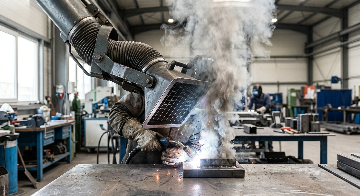
- Released at low velocity into moderately still air (welding, low-speed grinding, container filling): 100–200 FPM
- Active generation into rapid air motion (spraying, conveyor loading, crushing): 200–500 FPM
- High initial velocity into very turbulent air (heavy grinding, abrasive blasting, tumbling): 500–2,000 FPM
Multiply the required capture velocity by the cross-sectional area of the imaginary “control envelope” in front of the hood and you get CFM at that pickup. A 24" x 18" downdraft welding table needing 150 FPM at the surface? That is 3 sq ft × 150 = 450 CFM per table. Add hoods, sum them up, and you have your process airflow before any duct losses.
Calculating Total System CFM (Without Fooling Yourself)
Here is where most spreadsheets quietly lie. Total system CFM is not just the sum of hood CFMs — you have to account for branches that run simultaneously, leakage, and a safety margin for filter loading.
The honest formula
Total design CFM = (Σ simultaneous hood CFM) × 1.10 leakage factor × 1.10–1.20 dirty-filter margin.
That second margin matters. A pulse-jet cartridge collector pulls rated CFM with clean filters at maybe 1" w.g. of resistance. At end-of-life loading you may be at 6" w.g. — and the fan curve drops airflow at higher static pressure. If you sized the fan exactly at clean-filter conditions, you are running 20% under spec by month six.
Real example
A fabrication shop runs five robotic weld cells (800 CFM each) plus two manual grinding booths (1,200 CFM each). All seven run simultaneously. Naive total: 6,400 CFM. With factors: 6,400 × 1.10 × 1.15 ≈ 8,100 CFM. That is the fan you actually need to spec — not the 6,400 the brochure math gave you. For a deeper look at picking the right unit by application, see our guide on key factors for dust collection equipment selection.
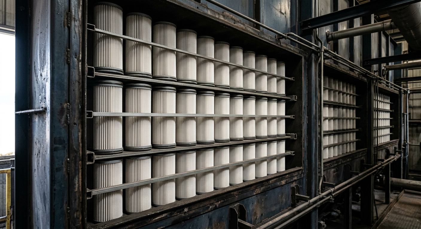
Air-to-Cloth Ratio: The Number Everyone Gets Wrong
The air-to-cloth ratio (A/C) is CFM divided by total filter media area in square feet. Units are FPM, but think of it as “how hard you are pushing air through the fabric.” Push too hard and you blind the media, blow dust cake off prematurely, and watch differential pressure climb.
Recommended ratios by dust type
- Pulse-jet cartridge, fine fume (welding, laser cutting, plasma): 1.5–2.0:1
- Pulse-jet cartridge, general nuisance dust: 2.0–2.5:1
- Pulse-jet baghouse, heavy granular (wood, grain): 4.0–6.0:1
- Reverse-air baghouse, sticky or hygroscopic: 1.5–2.0:1
- Shaker baghouse: 1.5–2.5:1
A common vendor trick: quoting net A/C while excluding the filters being cleaned during pulse cycles. On a six-row cartridge unit pulsing one row at a time, your net filtration area is 5/6 of gross. If you do not adjust, you are running 20% harder than you think.
Quick worked example
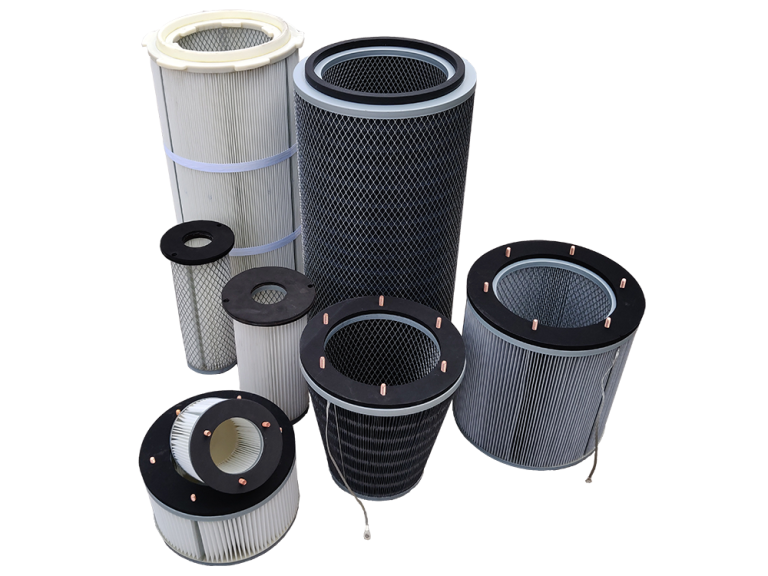
You need 8,100 CFM on welding fume. Target A/C of 1.8:1 means 8,100 ÷ 1.8 = 4,500 sq ft of net cloth. With 226 sq ft per cartridge (typical 26" nano-fiber), that is 4,500 ÷ 226 ≈ 20 cartridges net, or 24 gross if you pulse one row of four. Round up — never down.
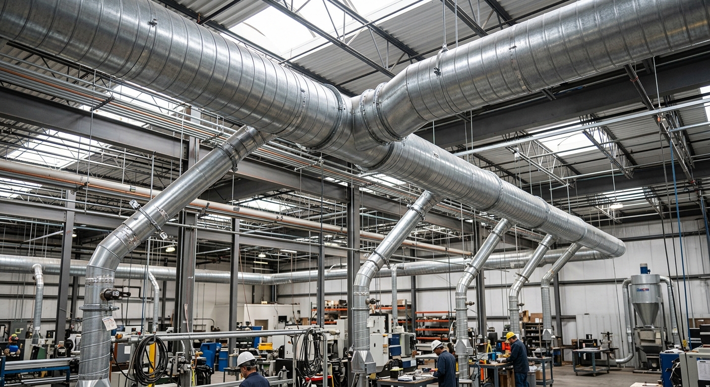
Ductwork: Transport Velocity Is Non-Negotiable
You can size the perfect collector and still fail because of duct. Dust settles when air slows down. Period. Each material has a minimum transport velocity below which particles drop out and accumulate in horizontal runs — eventually choking the system or, with combustible dust, becoming a fuel source.
Minimum transport velocities
- Vapors, gases, smoke: 1,000–2,000 FPM
- Very fine light dust (cotton lint, wood flour): 2,500–3,000 FPM
- Fine dry dusts (fine rubber, jute lint, buffing): 3,000–4,000 FPM
- Average industrial dusts (grinding, coffee, granite, brick cutting): 3,500–4,500 FPM
- Heavy dusts (sawdust, metal turnings, lead, cement): 4,500–5,500 FPM
- Heavy or moist: 5,500 FPM and up
Round duct, not rectangular. Long-radius elbows (centerline radius ≥ 1.5× diameter), not mitered. Lateral entries at 30°, not 90°. These are not preferences — they are the difference between a system that balances and a system that howls and clogs.
Where rookies blow it
Oversizing the main “to keep static low” drops velocity, drops dust, plugs the duct. A 12" main carrying 3,500 CFM runs at 4,456 FPM — fine. Bump it to 14" for “future expansion” and you are at 3,275 FPM, which is below transport velocity for most metal grinding dust. Six months later, you have 200 lbs of fines sitting in a horizontal run.
Static Pressure: The Number That Sets Your Fan
CFM tells you the fan size; static pressure (SP) tells you the fan horsepower. Total system SP is the sum of:
- Hood entry loss (varies by hood design — 0.25 to 1.75 VP)
- Acceleration loss (1.0 velocity pressure)
- Straight duct friction (use SP/100 ft tables or the Darcy equation)
- Fitting losses (elbows, entries, transitions — expressed as loss coefficients × VP)
- Filter resistance, clean and dirty (typically 1" w.g. clean, 6" w.g. dirty for cartridges)
- Stack or discharge loss
Add it all up. A typical small-to-mid metalworking dust collection system lands between 8" and 14" w.g. total SP. Pick the fan from the manufacturer's curve at your design CFM and dirty-filter SP — not the clean number. Choose backward-inclined or radial-tipped wheels for clean side, radial-blade if the fan sits on the dirty side (rare, but it happens with some pre-separator setups).
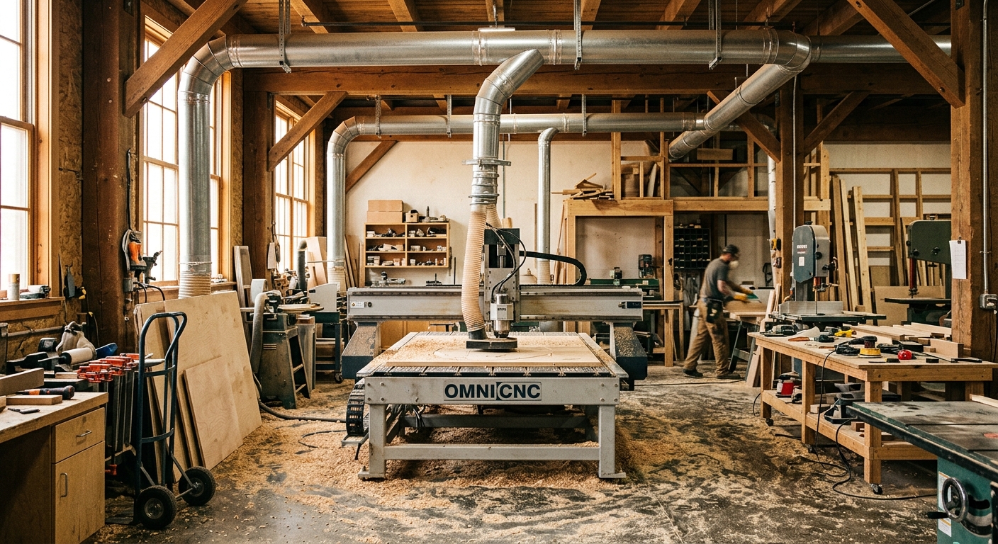
Real-World Case: Resizing a Choked Woodshop System
A 14-machine cabinet shop called us because their existing 7.5 HP collector “was not pulling like it used to.” The customer assumed a worn impeller. The actual problems, in order of impact:
- Original design totaled hood CFMs assuming only 50% simultaneity. The shop had grown and now ran 11 machines at once.
- The 8" main had been extended with two 90° mitered elbows to reach a new CNC router. Velocity dropped from 4,200 FPM to about 3,400 FPM, and sawdust was settling in the horizontal run above the assembly area.
- A/C ratio on the bag filter was 4.8:1 — fine for the original load, but with finer MDF dust now dominating, blinding accelerated and dirty-filter SP had climbed to 9" w.g.
The fix: oversize the fan to 15 HP at 8,200 CFM and 12" SP, rebuild the main as 10" with long-radius elbows, drop A/C to 3.5:1 by adding bag area, and split the trunk into two balanced branches. Total dust capture went from intermittent to spec, and filter life tripled. The lesson: when a system “weakens,” the fan is usually fine — the design assumptions have drifted. For more on this category of fixes, our breakdown of the top four dust collection system types is a useful starting point.
Special Cases: Combustible, Hygroscopic, and Fine Fume
Standard tables get you 80% of the way. The remaining 20% is where systems blow up — sometimes literally.
Combustible dust (Kst > 0)
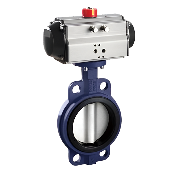
If your dust has a Kst value, NFPA 652/660 applies. Sizing must include explosion venting or suppression, isolation valves on the duct, and ducts designed to withstand or relieve a deflagration. Transport velocity often needs to climb to keep concentration below the minimum explosible concentration (MEC) — typically 25% of MEC as a working limit. Grain handlers know this pain well; we covered it in mitigating dust disasters in grain handling facilities.
Hygroscopic or sticky dusts
Sugar, salt, some pharma APIs. Drop A/C ratio aggressively — 1.2–1.5:1 is not unusual. Insulate duct externally to prevent condensation. Consider PTFE-membrane media. Cleaning a caked-on hygroscopic dust from a baghouse is a job nobody wants twice.
Submicron fume
Laser, plasma, lithium battery electrode dust. Cartridges with nano-fiber surface loading and a HEPA after-filter. See our deep dives on dust collection in lithium battery production and pharmaceutical GMP dust collection for the gory details on containment.
A Sizing Checklist You Can Actually Use
Run through this before signing any PO:
- Have you measured or estimated capture velocity at every hood, not assumed a global number?
- Did you apply simultaneity correctly — and honestly?
- Did you add leakage (10%) and dirty-filter (15–20%) margins to CFM?
- Is the A/C ratio appropriate for your dust type and quoted as net, not gross?
- Are all duct branches above minimum transport velocity for your specific dust?
- Long-radius elbows? 30° entries? Round duct? Balanced trunk?
- Did you size the fan against dirty-filter SP, not clean?
- If combustible, is the design code-compliant with isolation and venting?
- Is there a sensible filter monitoring strategy — DP gauge minimum, ideally with logging?
Tick every box. Skipping one tends to surface as an angry phone call eighteen months later.
Get the Numbers Right the First Time
Sizing a dust collector is not magic — it is arithmetic with a few non-negotiable rules. Start at the hood, work outward, respect transport velocity, give the filter media room to breathe, and never spec a fan against clean-filter conditions. Do that and the system disappears into the background of your operation, which is exactly what good dust collection should do.
If you would rather not handle the calculations yourself — or you want a second pair of eyes on a design before you cut steel — the engineering team at villotech sizes systems like this every week, across welding, pharma, battery, woodworking, and grain. Send us your equipment list and dust data, and we will give you the CFM, A/C, and duct schedule with the assumptions laid out so you can challenge them.